

 icon is filled in, this means that there are voxels in the current asset which have been painted with the related class.
By clicking on the
icon is filled in, this means that there are voxels in the current asset which have been painted with the related class.
By clicking on the  eye icon next to a class name, you can hide brush traces belonging to the class. Clicking on the three dots and then on the
  trash can will delete all segmentations from the class.
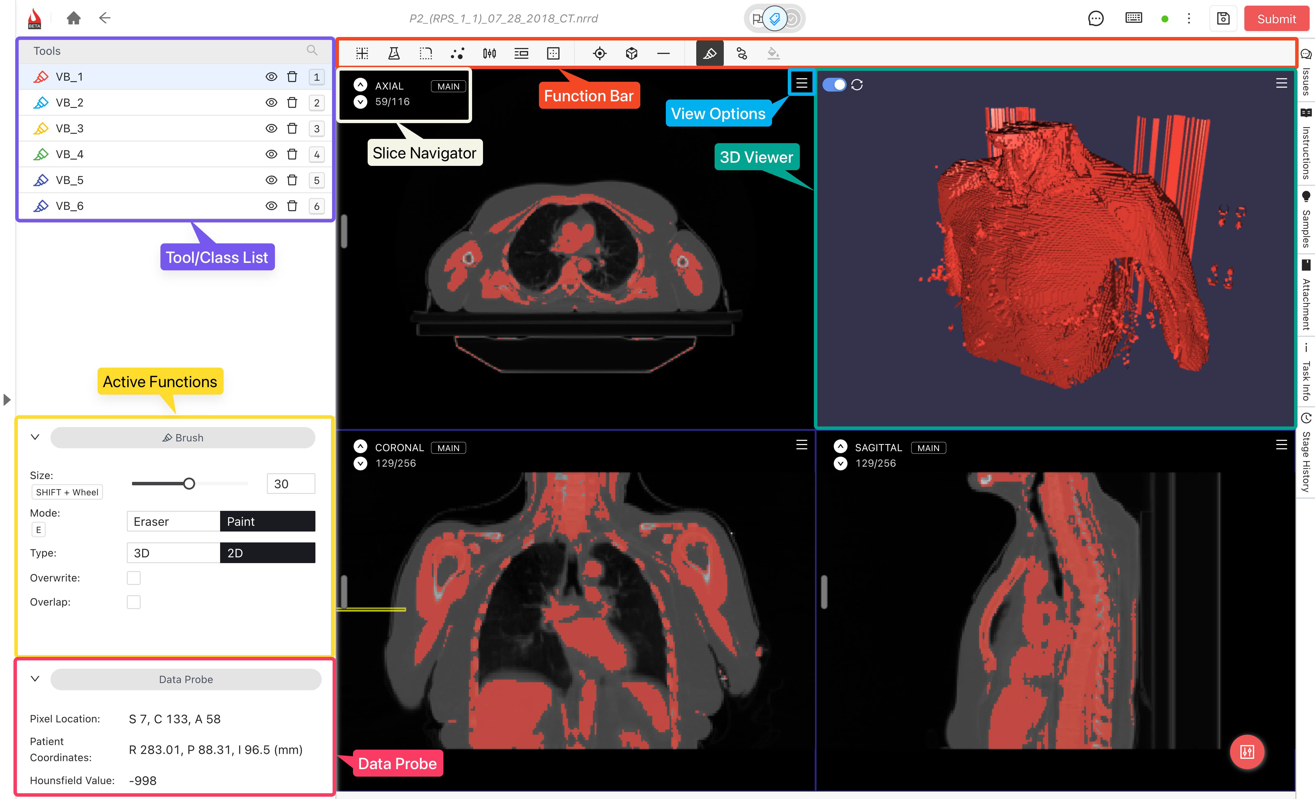
Once a class is selected, you can annotate on the asset using its functions – brush, pen, threshold, and more, by clicking on the function from the *Function Bar*.
#### Jumping to a class's largest segmentation in all views
Click on the three dots next to the class name and then on Jump. All visible views will jump to the slice containing the highest amount of voxels painted with the class you specified.
trash can will delete all segmentations from the class.
Once a class is selected, you can annotate on the asset using its functions – brush, pen, threshold, and more, by clicking on the function from the *Function Bar*.
#### Jumping to a class's largest segmentation in all views
Click on the three dots next to the class name and then on Jump. All visible views will jump to the slice containing the highest amount of voxels painted with the class you specified.


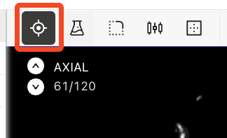
 **Crosshair Toggle**: toggles the crosshair on or off.\
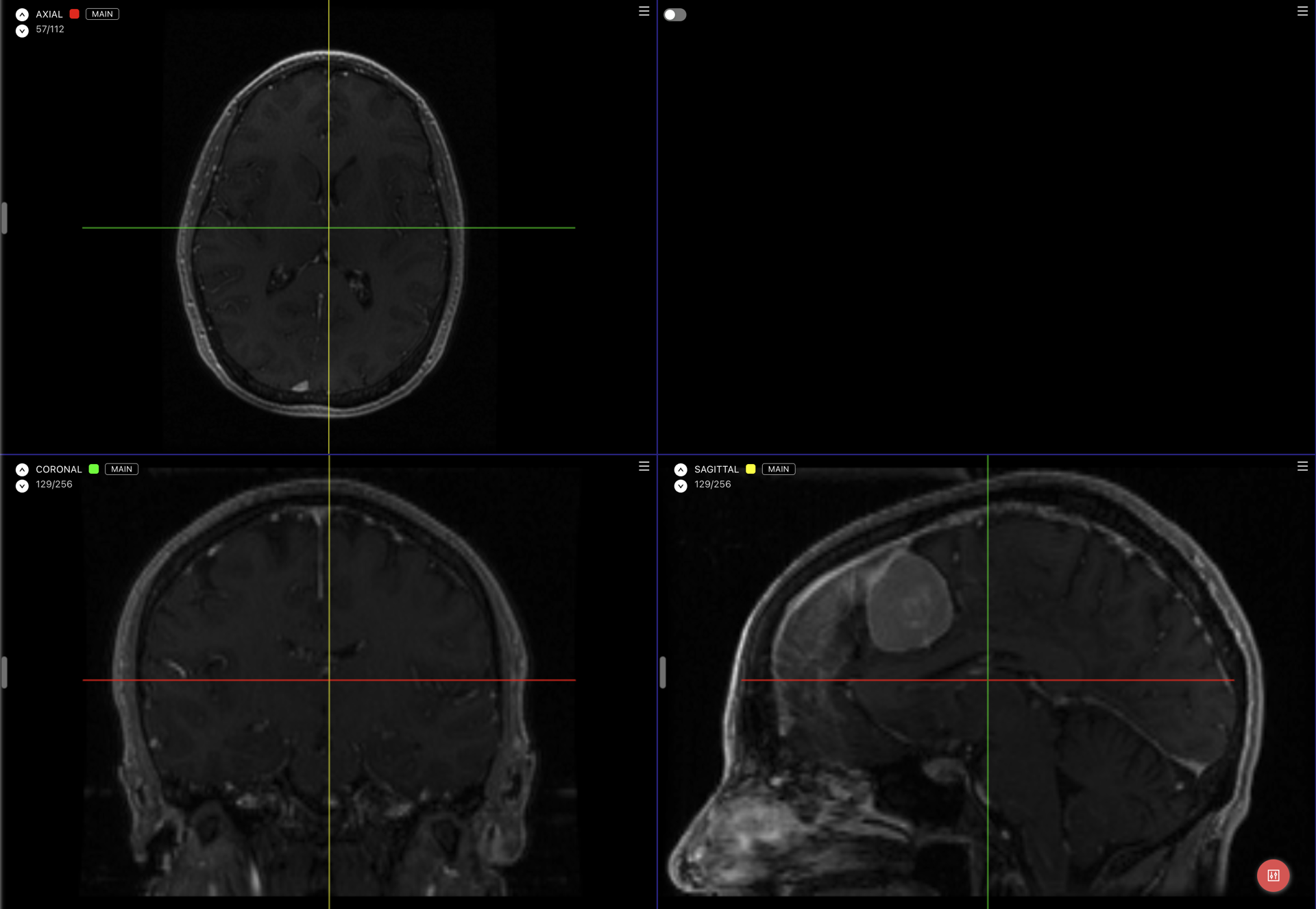
Read more about the crosshair [here](#multi-planar-translation-and-crosshair).
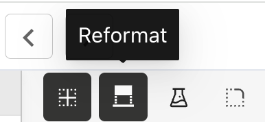
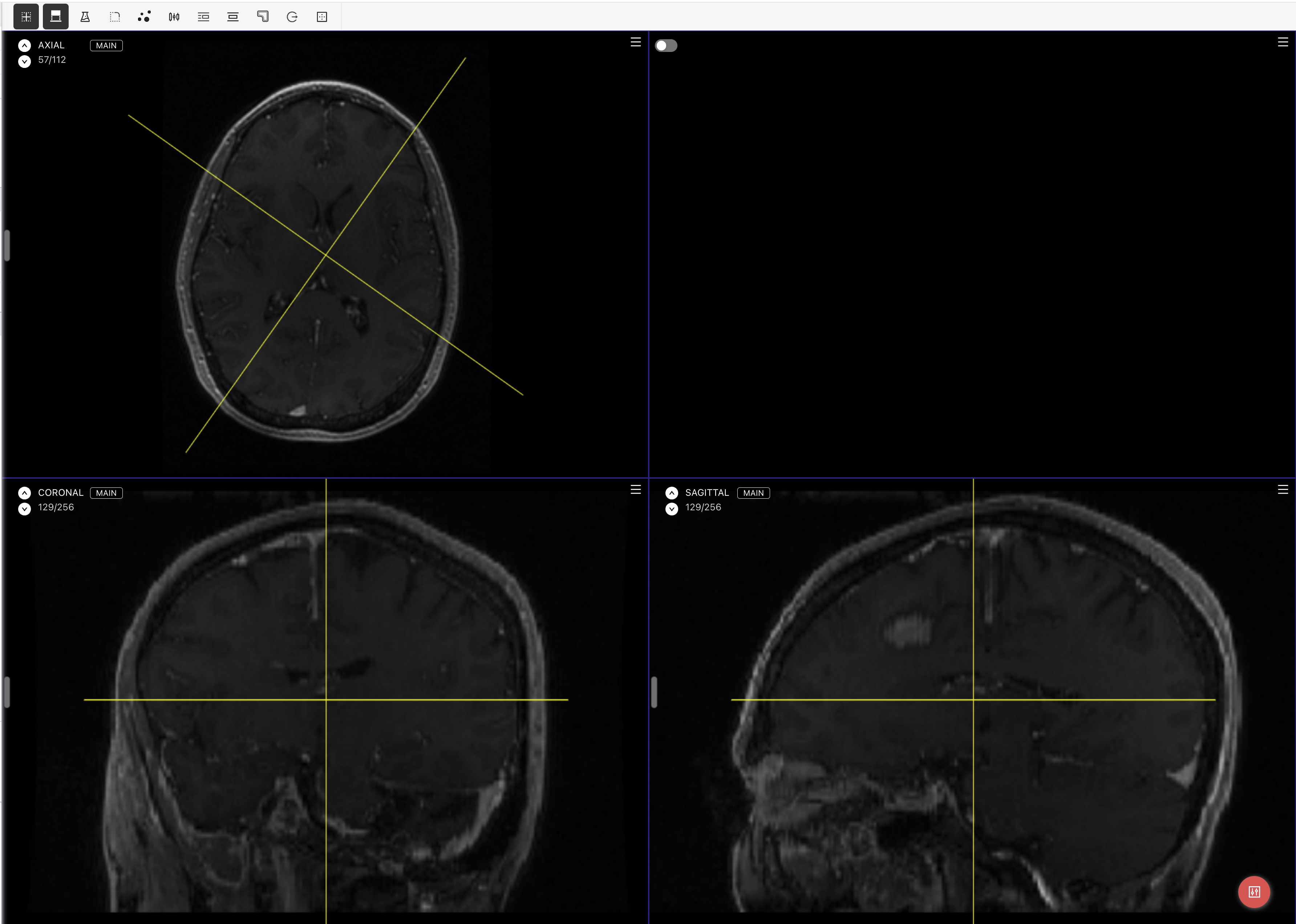
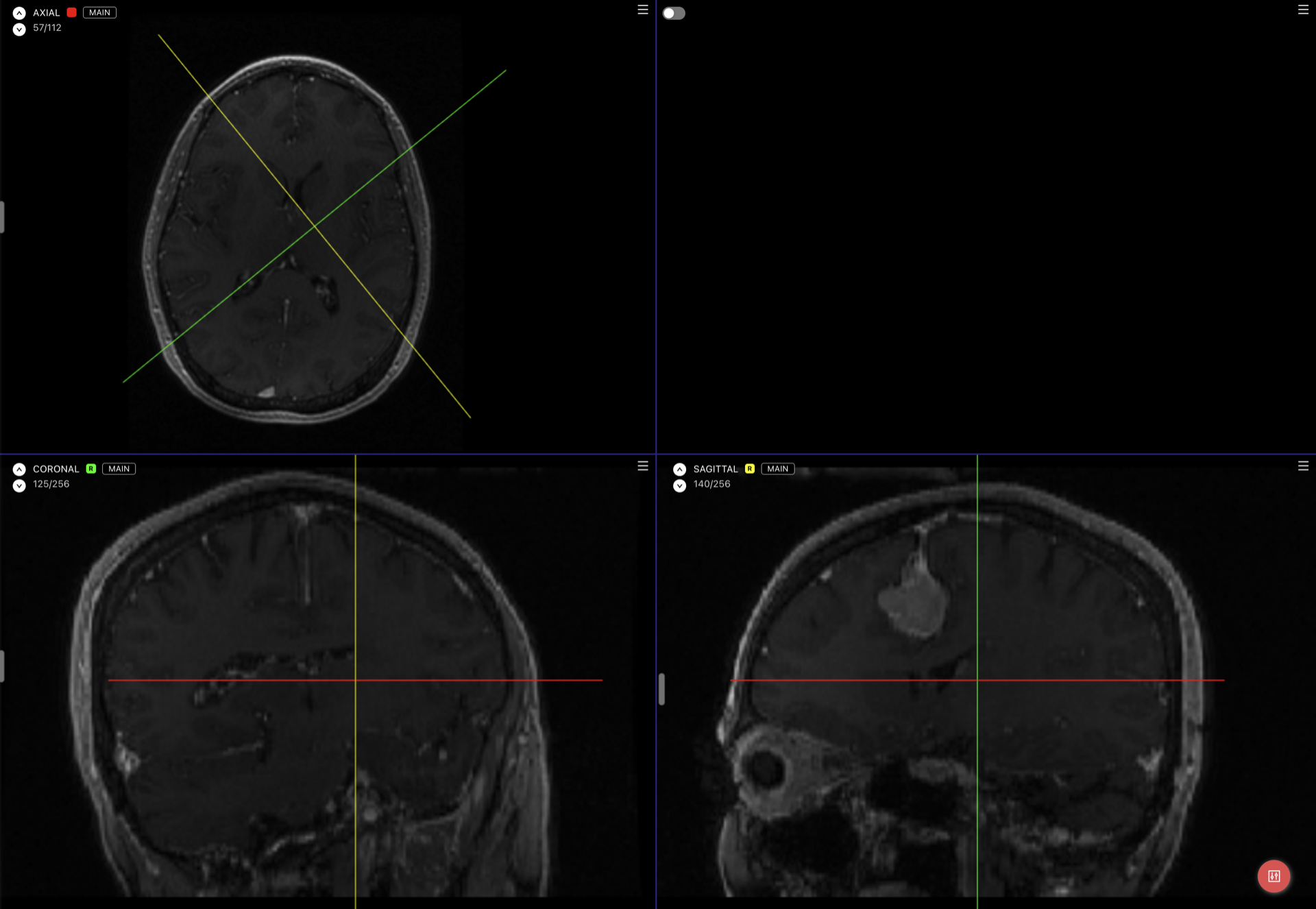
* **Reformat**: toggles oblique reformat mode for NRRD assets.\
Read more about Reformat [here](#reformat).
*
**Crosshair Toggle**: toggles the crosshair on or off.\
Read more about the crosshair [here](#multi-planar-translation-and-crosshair).
* **Reformat**: toggles oblique reformat mode for NRRD assets.\
Read more about Reformat [here](#reformat).
*  **Window Options**: Change the window width and level.\
Read more about window options [here](#windowing-options).
*
**Window Options**: Change the window width and level.\
Read more about window options [here](#windowing-options).
*  **Smoothing**: Opens the *Smoothing* tool, allowing you to smooth out your annotations.\
Read more about smoothing [here](#smoothing).
*
**Smoothing**: Opens the *Smoothing* tool, allowing you to smooth out your annotations.\
Read more about smoothing [here](#smoothing).
*  **Island Tools**: Tools related to deleting and changing categories of islands.\
Read more about island tools [here](#island-tools).
*
**Island Tools**: Tools related to deleting and changing categories of islands.\
Read more about island tools [here](#island-tools).
*  **Threshold Tool**: Paint all pixels with values falling between two values you specify.\
Read more about threshold [here](#threshold).
*
**Threshold Tool**: Paint all pixels with values falling between two values you specify.\
Read more about threshold [here](#threshold).
*  **Logical Operators**: Perform logical operation on labeling classes, like invert, subtract, add, copy, and more.\
Read more about logical operators [here](#logical-operators).
* **Fill Between Slices**: read more about this function [here](/labeling/labeling-editor-interface/medical-labeling-editor/fill-between-slices.md).
* **Level Tracing**: With a labeling tool selected, press `T` or click the Level Tracing button to toggle it on or off. When toggled on, hovering on a voxel will display a trace of the voxels at the same level of the hovered voxel. Clicking confirms the selection.
*
**Logical Operators**: Perform logical operation on labeling classes, like invert, subtract, add, copy, and more.\
Read more about logical operators [here](#logical-operators).
* **Fill Between Slices**: read more about this function [here](/labeling/labeling-editor-interface/medical-labeling-editor/fill-between-slices.md).
* **Level Tracing**: With a labeling tool selected, press `T` or click the Level Tracing button to toggle it on or off. When toggled on, hovering on a voxel will display a trace of the voxels at the same level of the hovered voxel. Clicking confirms the selection.
*  **Grow**: When toggled on, click and drag on the asset to perform a "grow" motion. You may alter the sensitivity of this tool from the settings on the left-hand side of the screen. If you wish to limit the effect of the grow tool to a specific Hounsfield unit range, also activate the Threshold function and select your range.
* **Grow from Seeds**: create a 3D segmentation from painted seed strokes, review a preview, and apply the result. Read more [here](/labeling/labeling-editor-interface/medical-labeling-editor/grow-from-seeds.md).
* **Hollow**: turn a Voxel Brush segmentation into a 3D shell with a chosen thickness. Read more [here](/labeling/labeling-editor-interface/medical-labeling-editor/hollow.md).
* **Extract Centerline**: create a 3D polyline through a segmented vessel between two chosen endpoints. Select a Voxel Brush class to enable it. Read more [here](/labeling/labeling-editor-interface/medical-labeling-editor/extract-centerline.md).
*
**Grow**: When toggled on, click and drag on the asset to perform a "grow" motion. You may alter the sensitivity of this tool from the settings on the left-hand side of the screen. If you wish to limit the effect of the grow tool to a specific Hounsfield unit range, also activate the Threshold function and select your range.
* **Grow from Seeds**: create a 3D segmentation from painted seed strokes, review a preview, and apply the result. Read more [here](/labeling/labeling-editor-interface/medical-labeling-editor/grow-from-seeds.md).
* **Hollow**: turn a Voxel Brush segmentation into a 3D shell with a chosen thickness. Read more [here](/labeling/labeling-editor-interface/medical-labeling-editor/hollow.md).
* **Extract Centerline**: create a 3D polyline through a segmented vessel between two chosen endpoints. Select a Voxel Brush class to enable it. Read more [here](/labeling/labeling-editor-interface/medical-labeling-editor/extract-centerline.md).
*  **Borders**: Toggle whether the brush traces shown should be filled in or not. The change is merely cosmetic and has no bearing on the export.
*
**Borders**: Toggle whether the brush traces shown should be filled in or not. The change is merely cosmetic and has no bearing on the export.
*  **Keypoints**: When enabled, clicking anyhere on the view creates a new keypoint.\
Read more about keypoints [here](#keypoints).
*
**Keypoints**: When enabled, clicking anyhere on the view creates a new keypoint.\
Read more about keypoints [here](#keypoints).
*  **3D Bounding Box**: When enabled, clicking and dragging on the asset will create a 3D bounding box. Read more about 3D bounding boxes [here](/labeling/labeling-editor-interface/medical-labeling-editor/3d-bounding-box.md).
*
**3D Bounding Box**: When enabled, clicking and dragging on the asset will create a 3D bounding box. Read more about 3D bounding boxes [here](/labeling/labeling-editor-interface/medical-labeling-editor/3d-bounding-box.md).
*  **Slice Navigator**: Slider allowing you to move between slices in the view. Drag the slider up and down to move between slices, or click on the up and down arrows on the top left of the view. Additionally containing the name of the current view, current slice/total number of slices, and in [assets with reference volumes](/data/importing-assets/importing-reference-medical-data-during-asset-import.md), whether the currently-viewed volume is a main or a reference one.
Additionally, when a tool is selected:
*
**Slice Navigator**: Slider allowing you to move between slices in the view. Drag the slider up and down to move between slices, or click on the up and down arrows on the top left of the view. Additionally containing the name of the current view, current slice/total number of slices, and in [assets with reference volumes](/data/importing-assets/importing-reference-medical-data-during-asset-import.md), whether the currently-viewed volume is a main or a reference one.
Additionally, when a tool is selected:
*  **Brush Tool**: Create a segmentation by painting.
*
**Brush Tool**: Create a segmentation by painting.
*  **Pen Tool**: Create a segmentation by drawing a closed loop.
*
**Pen Tool**: Create a segmentation by drawing a closed loop.
*  **Adaptive Brush**: When active, the shape of the brush will act as a "bucket" tool. You may change the sensitivity of this tool from the left-hand side of the screen.
### 3D Viewer
By enabling the 3D toggle, you'll be able to see a 3D reconstruction of the annotations completed so far in the top-right view, including supported medical objects such as points, polylines, polygons, bounding boxes, rotated bounding boxes, and voxel brush traces.
* Rotate the view by dragging with the mouse cursor
* Zoom in and out with the scroll wheel
* Pan with Ctrl + Left Mouse Button
After editing annotations in the 2D views, click on the refresh
**Adaptive Brush**: When active, the shape of the brush will act as a "bucket" tool. You may change the sensitivity of this tool from the left-hand side of the screen.
### 3D Viewer
By enabling the 3D toggle, you'll be able to see a 3D reconstruction of the annotations completed so far in the top-right view, including supported medical objects such as points, polylines, polygons, bounding boxes, rotated bounding boxes, and voxel brush traces.
* Rotate the view by dragging with the mouse cursor
* Zoom in and out with the scroll wheel
* Pan with Ctrl + Left Mouse Button
After editing annotations in the 2D views, click on the refresh  button in the top left of the 3D view to update the reconstruction. Scissors cuts, and undo/redo while Scissors is active, update the 3D view automatically.



 .
.

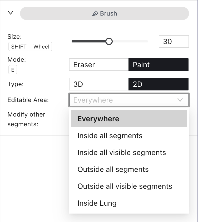
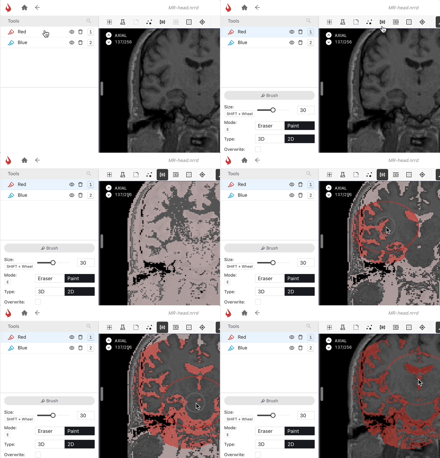


 ). From the dialog that appears on the left side of the screen, select the threshold range. Then, from the *Editable Area* dropdown, select the brush you have used to draw the initial area.
Ensure the 'Overwrite' or 'Overlap' toggle is on for the brush to run the threshold with, then click on Apply. Threshold will be applied in the area.
### Pen
The Pen tool allows you to draw a region of pixels to paint, similar to the [Segmentation](/labeling/labeling-tools/tools/segmentation.md) tool for images.
The pen tool is a subset of the Medical Brush tool. To activate the pen tool, first select a Medical Brush tool from the toolbar on the left, then click on the *Pen* button.
). From the dialog that appears on the left side of the screen, select the threshold range. Then, from the *Editable Area* dropdown, select the brush you have used to draw the initial area.
Ensure the 'Overwrite' or 'Overlap' toggle is on for the brush to run the threshold with, then click on Apply. Threshold will be applied in the area.
### Pen
The Pen tool allows you to draw a region of pixels to paint, similar to the [Segmentation](/labeling/labeling-tools/tools/segmentation.md) tool for images.
The pen tool is a subset of the Medical Brush tool. To activate the pen tool, first select a Medical Brush tool from the toolbar on the left, then click on the *Pen* button.

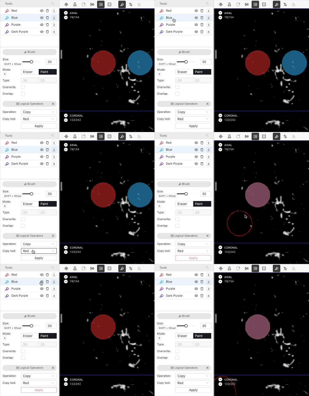
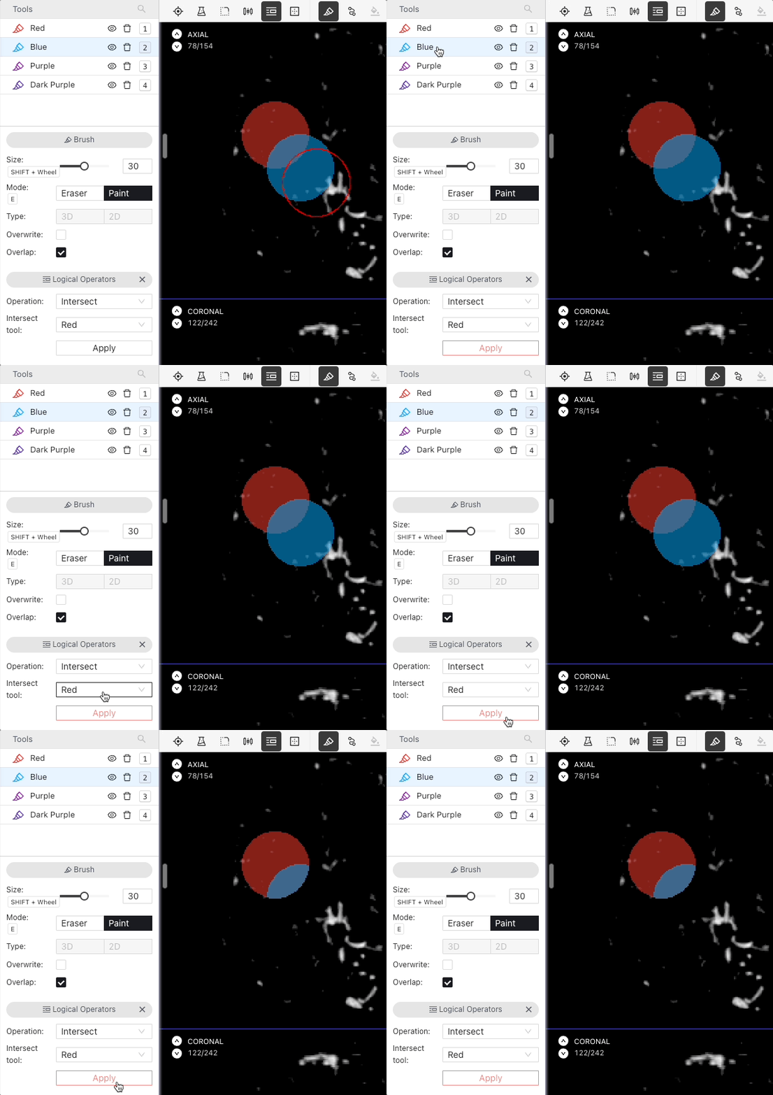
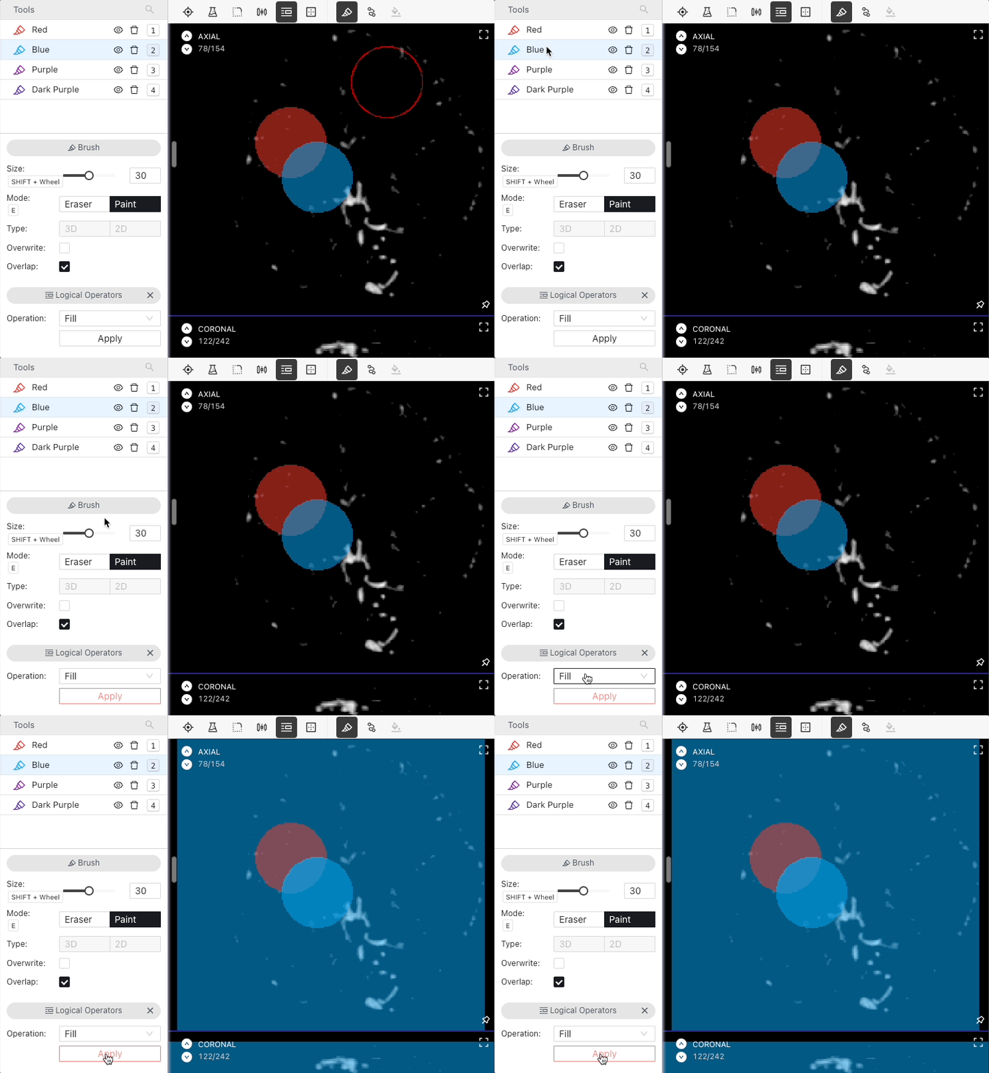
 ) and select an operation. If required by the operation, select the target tool. Then click on *Apply*.





 button to enable placing keypoints on the asset. Clicking anywhere on the asset will place a keypoint with three-dimensional coordinates:
{% @arcade/embed url="
button to enable placing keypoints on the asset. Clicking anywhere on the asset will place a keypoint with three-dimensional coordinates:
{% @arcade/embed url="| Condition | Shortcut | Action | Description |
|---|---|---|---|
| Always | Space + Drag Cursor | Pan | Pans the view. |
| Always | Ctrl + Mouse Wheel | Zoom | Zooms the view being currently hovered by the mouse cursor. |
| Always | Shift + Move Cursor | Multiplanar Translation | Navigates between slices in all other views to show the pixel you are hovering over in all views. |
| Always | Ctrl + Z | Undo | Undo the last action. |
| Always | Ctrl + Shift + Z | Redo | Redo the last undone action. |
| Always | Mouse Wheel | Navigate Slices | Move up and down between slices. |
| Always | Middle Mouse Button | Pan | Pans the view. |
| Always, except while typing in an input field | Shift + 1–8 | Apply Window Preset | Applies the corresponding predefined or saved custom window/level preset to the active view. |
| When no labeling tools are selected | Click and Drag | Pan | Pans the view. |
| When no labeling tools are selected | Double Click | Full Screen | Switch between the chosen layout and a single-view mode. |
| When a labeling tool is selected | Shift + Mouse Wheel | Change Tool Size | Changes the size of the tool. |
| When a labeling tool is selected, except while typing in an input field | T | Toggle Level Tracing | Turns Level Tracing on or off. |
| When a labeling tool is selected | W and Q | Change Tool | Move up and down in the tool list, changing the currently active tool. |
| When the "Window" icon is selected | Drag cursor up/down | Change Brightness | Dragging the cursor downwards will increase the brightness, dragging it upwards will decrease it. |
| When the "Window" icon is selected | Drag cursor left/right | Change Contrast | Moving the cursor to the left while holding Ctrl will increase contrast, moving it to the right will decrease it. |
| When the "Pen" tool is selected | N | Close Pen Trace | Closes the loop drawn with the pen and paints the pixels found inside it. |
